|
Recovery
and Restoration of a T1509 Transmitter part 3. December 2005 |
|
|
Back at
blighty the wiring loom was dismantled, carefully noting where
everything went and the damaged cables removed. I was surprised to
find that when stretched out, the loom is 8 feet long. The 550
volt wiring was replaced with some heavy duty (Artic) mains flex, and
the 1600 volt one with some UR67 coax with the braiding stripped out and
the inner threaded back through the outer.
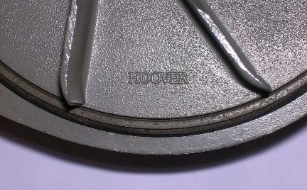
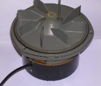
The fan was dismantled and checked over, it was in good condition but had a pair of 350 volt 0.1uF capacitors from each side to the frame. As the fan runs directly from the mains I thought it prudent to replace these with modern "X-caps". Testing the fan - it about blew everything off the bench so it worked OK, but boy was it noisy. I then noticed the manufacturer's name on the casting - that should explain all! <The fan and a closeup of the manufacturer's name!. |
 |
The T1509
audio system is on a separate and easily removable chassis so I took the
opportunity to check it over at home as well, bearing in mind the
problems that have been reported in this area by Richard and Stuart (here
if you've forgotten already!). It was in very good condition, and
looks as if all the original wiring (presumably rubber covered) had been
replaced with yellow pvc wire at some time in the past. Borrowing power
from a Linear Concord amplifier I powered it up and found it to be in
working order except for a very noisy gain control. This had to be
replaced, as were one or two slightly suspect coupling
capacitors.
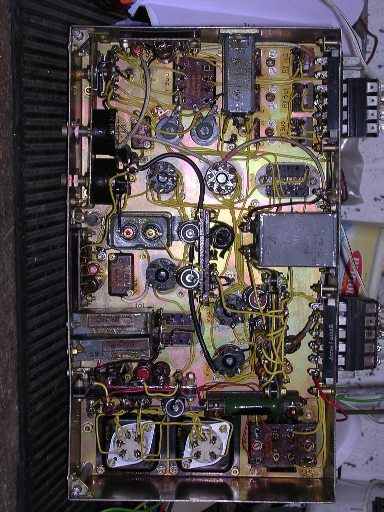
<Underside view of the speech amplifier |
 |
Feeding
in a sinewave from a signal generator I discovered an odd effect.
Now, the T1509 is designed to be run by remote control over a 600 ohm
line, and the audio amplifier has a muting system to cut it off in the
absence of audio on the line, to prevent transmission of extraneous line
noise. it also has audio avc (automatic volume control) to
compensate for differing line conditions and ooerator voice
levels. I like audio avc - everyone should use it - but this one
had an odd effect. Sure enough, the amplifier remained muted until
the input exceeded a certain level, but as the input level was
increased, the audio level remained constant up to a point as expected,
then fell again back to zero. A look at the circuit diagram
revealed all - the avc amplifier is fed direct from the input and this
is "open loop". Too much audio in caused it to reduce
the gain of the controlled stage to zero. A simple mod re-rerouted
the input to the avc amp to the output of the controlled stage,
resulting in a "closed loop" avc system and a very nice
control characteristic. I'm not fond of modifying original
designs, but I think there was a design error here....
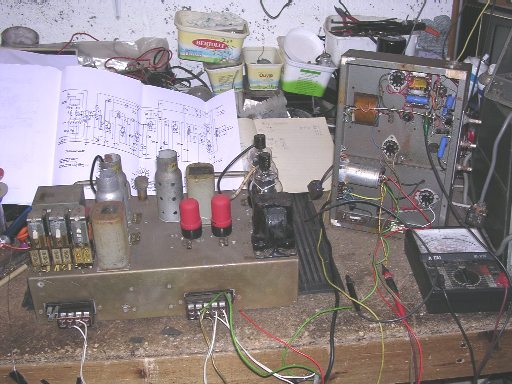
<Speech amplifier during testing at G4DDI QTH |
 |
The
next trip to Thorpe Camp was on December 17th, another cold damp
morning. This time I didn't bother with the GRC9, but I did take a
recently refurbished R209 receiver with which to listen to the AM
net. It's not a receiver I particularly like - it's
stability is so poor as to make it virtually useless on CW, but it did
perform well on the AM net.
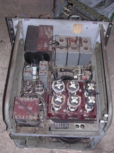
The fan and wiring loom was re-fitted to the cabinet, a new mains lead made up and the fan tested in situ. That removed most of the dust! I then set to on replacing the rectifier bases, damaged wiring and fuseholders in the power unit. That was another day's work done! <The refurbished psu - ready to go.
|